
Connections of a SPD to the loads should be as short as possible in order to reduce the value of the voltage protection level (installed Up) on the terminals of the protected equipment.
The total length of SPD connections to the network and the earth terminal block should not exceed 50 cm.
One of the essential characteristics for the protection of equipment is the maximum voltage protection level (installed Up) that the equipment can withstand at its terminals. Accordingly, a SPD should be chosen with a voltage protection level Up adapted to protection of the equipment (see Fig. 1). The total length of the connection conductors is
L = L1+L2+L3.
For high-frequency currents, the impedance per unit length of this connection is approximately 1 µH/m
Hence, applying Lenz's law to this connection: ΔU = L di/d
The normalized 8/20 µs current wave, with a current amplitude of 8 kA, accordingly creates a voltage rise of 1000 V per metre of cable.
ΔU =1 x 10-6 x 8 x 103 /8 x 10-6 = 1000 V
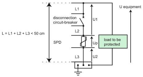
Fig. 1 – Connections of a SPD L < 50 cm
As a result the voltage across the equipment terminals, U equipment, is:
U equipment = Up + U1 + U2
If L1+L2+L3 = 50 cm, and the wave is 8/20 µs with an amplitude of 8 kÂ, the voltage across the equipment terminals will be Up + 500 V.
Connection in plastic enclosure
Figure 2 below shows how to connect a SPD in plastic enclosure.
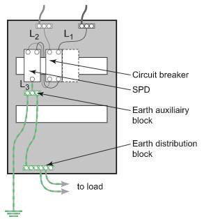
Fig. 2 – Example of connection in plastic enclosure
Connection in metallic enclosure
In the case of a switchgear assembly in a metallic enclosure, it may be wise to connect the SPD directly to the metallic enclosure, with the enclosure being used as a protective conductor (see Fig. 3).
This arrangement complies with standard IEC 61439-2 and the Assembly manufacturer must make sure that the characteristics of the enclosure make this use possible.
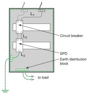
Fig. 3 – Example of connection in metallic enclosure
Conductor cross section
The recommended minimum conductor cross section takes into account:
1. The normal service to be provided: Flow of the lightning current wave under a maximum voltage drop (50 cm rule).
Note: Unlike applications at 50 Hz, the phenomenon of lightning being high-frequency, the increase in the conductor cross section does not greatly reduce its high-frequency impedance.
2. The conductors' withstand to short-circuit currents: The conductor must resist a short-circuit current during the maximum protection system cutoff time.
IEC 60364 recommends at the installation incoming end a minimum cross section of:
a. 4 mm2 (Cu) for connection of Type 2 SPD;
b. 16 mm2 (Cu) for connection of Type 1 SPD (presence of lightning protection system).