

Surge Protection Devices (SPD) are used for
electric power supply networks, telephone networks, and communication and
automatic control buses.
The Surge Protection Device (SPD) is a
component of the electrical installation protection system.
This device is connected in parallel on the
power supply circuit of the loads that it has to protect (see Fig.1). It can
also be used at all levels of the power supply network.
This is the most commonly used and most
efficient type of overvoltage protection.
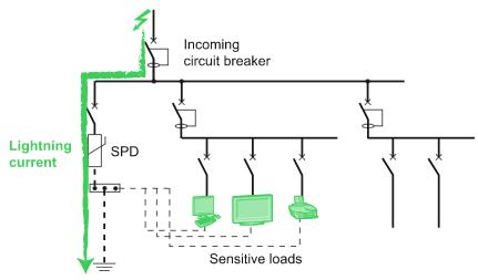
Fig.1 – Principle of protection system in parallel
SPD connected in parallel has a high impedance. Once the transient overvoltage appears in the system, the impedance of the device decreases so surge current is driven through the SPD, bypassing the sensitive equipment.
Principle
SPD is designed to limit transient overvoltages of atmospheric origin and divert current waves to earth, so as to limit the amplitude of this overvoltage to a value that is not hazardous for the electrical installation and electric switchgear and controlgear.
SPD eliminates overvoltages
=in common mode, between phase and neutral or earth;
=in differential mode, between phase and neutral.
In the event of an overvoltage exceeding the operating threshold, the SPD
=conducts the energy to earth, in common mode;
=distributes the energy to the other live conductors, in differential mode.
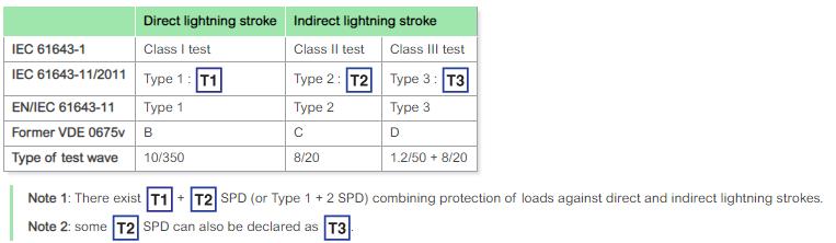
The three types of SPD
Type 1 SPD
The Type 1 SPD is recommended in the specific case of service-sector and industrial buildings, protected by a lightning protection system or a meshed cage.
It protects electrical installations against direct lightning strokes. It can discharge the back-current from lightning spreading from the earth conductor to the network conductors.
Type 1 SPD is characterized by a 10/350 µs current wave.
Type 2 SPD
The Type 2 SPD is the main protection system for all low voltage electrical installations. Installed in each electrical switchboard, it prevents the spread of overvoltages in the electrical installations and protects the loads.
Type 2 SPD is characterized by an 8/20 µs current wave.
Type 3 SPD
These SPDs have a low discharge capacity. They must therefore mandatorily be installed as a supplement to Type 2 SPD and in the vicinity of sensitive loads.
Type 3 SPD is characterized by a combination of voltage waves (1.2/50 μs) and current waves (8/20 μs).
SPD normative definition
Fig.2 – SPD standard definition
Characteristics of SPD
International standard IEC 61643-11 Edition 1.0 (03/2011) defines the characteristics and tests for SPD connected to low voltage distribution systems (see Fig.3).
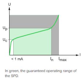
Fig.3 – Time/current characteristic of a SPD with varistor
Common characteristics
=Uc: Maximum continuous operating voltage
This is the A.C. or D.C. voltage above which the SPD becomes active. This value is chosen according to the rated voltage and the system earthing arrangement.
=Up: Voltage protection level (at In)
This is the maximum voltage across the terminals of the SPD when it is active. This voltage is reached when the current flowing in the SPD is equal to In. The voltage protection level chosen must be below the overvoltage withstand capability of the loads. In the event of lightning strokes, the voltage across the terminals of the SPD generally remains less than Up.
=In: Nominal discharge current
This is the peak value of a current of 8/20 µs waveform that the SPD is capable of discharging minimum 19 times.
Why is In important?
In corresponds to a nominal discharge current that a SPD can withstand at least 19 times: a higher value of In means a longer life for the SPD, so it is strongly recommended to chose higher values than the minimum imposed value of 5 kA.
Type 1 SPD
=Iimp: Impulse current
This is the peak value of a current of 10/350 µs waveform that the SPD is capable of discharging of discharging at least one time.
Why is Iimp important?
IEC 62305 standard requires a maximum impulse current value of 25 kA per pole for three-phase system. This means that for a 3P+N network the SPD should be able to withstand a total maximum impulse current of 100kA coming from the earth bonding.
=Ifi: Autoextinguish follow current
Applicable only to the spark gap technology. This is the current (50 Hz) that the SPD is capable of interrupting by itself after flashover. This current must always be greater than the prospective short-circuit current at the point of installation.
Type 2 SPD
=Imax: Maximum discharge current
This is the peak value of a current of 8/20 µs waveform that the SPD is capable of discharging once.
Why is Imax important?
If you compare 2 SPDs with the same In, but with different Imax: the SPD with higher Imax value has a higher "safety margin" and can withstand higher surge current without being damaged.
Type 3 SPD
=Uoc: Open-circuit voltage applied during class III (Type 3) tests.
Main applications
=Low Voltage SPD
Very different devices, from both a technological and usage viewpoint, are designated by this term. Low voltage SPDs are modular to be easily installed inside LV switchboards.
There are also SPDs adaptable to power sockets, but these devices have a low discharge capacity.
=SPD for communication networks
These devices protect telephone networks, switched networks and automatic control networks (bus) against overvoltages coming from outside (lightning) and those internal to the power supply network (polluting equipment, switchgear operation, etc.).
Such SPDs are also installed in RJ11, RJ45, ... connectors or integrated into loads.


